
Reading a Fracture Surface: What SEM Fractography Can Tell You
Dimples, cleavage, intergranular facets and fatigue marks: what each says about how a part broke, what the SEM can't tell you, and how to ship a broken part so the evidence survives.
When a part breaks, the fracture surface is a record of how it broke. Read carefully, it can show where the crack started, which direction it grew, whether it grew slowly over many load cycles or all at once, and whether it ran through the grains of the metal or between them. That is often the fastest route from "it broke" to a useful next question about material, design, loading, or environment.
This note covers what an SEM fracture analysis can tell you, what it can't, and how to handle a broken part so the evidence is still there when it reaches the microscope.
Start with the naked eye and a stereo microscope
Much of the useful information on a fracture surface is visible at low magnification. Before anything goes into the SEM, we look at the whole surface optically to find the origin: the point where the crack started. Radial marks run outward from it, chevron marks point back toward it, and beach marks curve around it. Ratchet marks, small steps along the edge, show where several cracks started and joined, which often points to high stress or a stress concentration. We also note how much of the surface is flat and how much is rough and torn. On a fatigue fracture, the flat region is usually the slow, progressive crack growth and the rough region the final overload, but a flat surface can also be a fast brittle fracture, so texture alone isn't enough. Finding the origin first tells us where to spend SEM time.
What the SEM adds
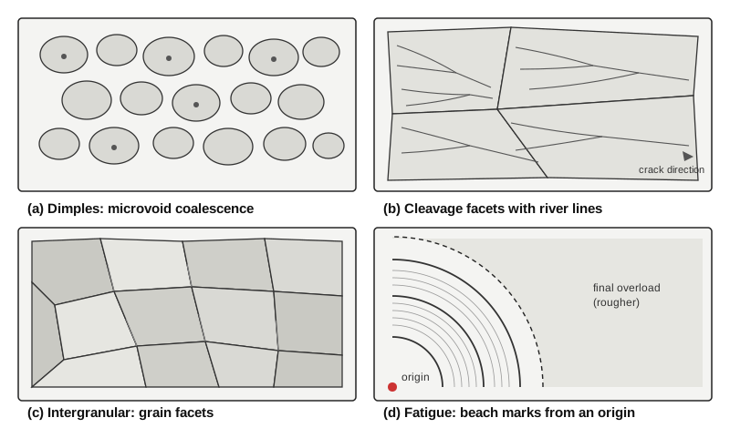
At higher magnification, the SEM shows the features that separate one fracture mode from another. The four you see most often in metals are sketched below.[1][2][3]
Dimples: ductile overload
A field of cup-shaped dimples means the metal tore apart by microvoid coalescence: small voids nucleated, grew, and joined. It is the typical signature of a part that was simply loaded past its strength. Elongated or tilted dimples point to shear or tearing rather than straight tension. Dimples also make up the final overload zone of most fatigue fractures, so finding them doesn't by itself mean the whole failure was a single overload.
Cleavage: brittle transgranular fracture
Flat facets crossed by branching "river" lines are cleavage, where the crack split the grains along specific crystal planes with little plastic deformation. Cleavage is typical of ferritic and other body-centered cubic steels at low temperature or high loading rates, and is rare in face-centered cubic metals such as austenitic stainless steel, aluminum, and copper. The river lines join together in the direction the crack ran, so following them back upstream leads toward where it came from.
Intergranular fracture
When the crack runs along grain boundaries, the surface looks faceted, sometimes described as "rock candy," with the faces of individual grains exposed. The boundaries were the weakest path through the metal. Hydrogen embrittlement, stress corrosion cracking, temper embrittlement, liquid metal embrittlement, grain-boundary precipitates, and creep can all produce it, and the morphology by itself does not tell them apart. That is where material history, environment, and sometimes chemistry come in.
Fatigue
Fatigue cracks grow a little with each load cycle. At low magnification they leave beach marks, curved bands that record pauses or changes in loading. Beach marks need the loading to change over time, so parts cycled at constant amplitude may not show them. At high magnification, many metals show striations, fine parallel lines where each line can correspond to a single load cycle. Striations are easiest to see in aluminum alloys and can be faint or absent in high-strength steels, so not finding them doesn't rule out fatigue. A fatigue surface usually ends in a rougher overload zone where the remaining cross-section could no longer carry the load, and a larger overload zone generally means the part was under higher stress when it failed.
What fractography can't tell you on its own
The fracture surface shows how a part broke. It rarely proves why by itself. Intergranular fracture consistent with hydrogen embrittlement, for example, is a strong lead, but confirming it usually means looking at the plating or cleaning process, hardness, and service environment. A fatigue origin at a sharp corner points to a stress concentration, but whether the root cause is the design, the machining, or an unexpected load is an engineering question. A good report says what the surface shows and stops there. The interpretation is a conversation with the people who know the part.
Polymers and ceramics fracture differently. Plastics can show crazing, fatigue striations, and stress whitening. Glasses and ceramics often show a smooth "mirror" zone around the origin, then "mist" and "hackle" as the surface roughens outward. The same approach applies: find the origin, then read the features around it.
How to handle and ship a broken part
Fracture surfaces are easy to damage and hard to recover. A few minutes of care before shipping makes a real difference:
- Don't fit the pieces back together. Mating the two halves can crush the fine features at the surface, including striations.
- Don't touch, brush, or clean the fracture surface. No wire brushes, solvents, or tape on the fracture. Fingerprints and cleaning both add contamination and can remove deposits that matter.
- Keep it dry. A fresh steel fracture can start to rust quickly in humid air, and rust hides fine features. Bag each piece separately with a desiccant pack if you have one.
- If you have to cut the part to ship it, cut well away from the fracture and keep it cool. Tell us where you cut.
- Don't mark or label on the fracture surface. Label the bag or the far end of the part instead.
- Pad the pieces so they can't move. Wrap each piece so nothing contacts the fracture surface, and box it so it can't rattle.
- Send a good part if you have one. An unbroken part from the same lot is a useful reference for material, surface finish, and coatings.
- Tell us the history. Material and any heat treatment or plating, how the part was loaded, how long it ran, the environment, and how many have failed. Context shapes what we look for.
Fracture surface analysis at Nano Lab
We image fracture surfaces optically and by SEM, with EDS when deposits, corrosion products, or inclusions need identifying, and cross-sections when the question calls for them. You get images of the origin and the features around it, with an observational report. Send a photo and a sentence about how the part failed, and we'll suggest a scope.
References
- ASM Handbook, Volume 12: Fractography, ASM International (1987).
- ASM Handbook, Volume 11: Failure Analysis and Prevention, ASM International (2021).
- D. Hull, Fractography: Observing, Measuring and Interpreting Fracture Surface Topography, Cambridge University Press (1999).